Article
Required Data and Survey Materials for the Design of Rockfall Barriers
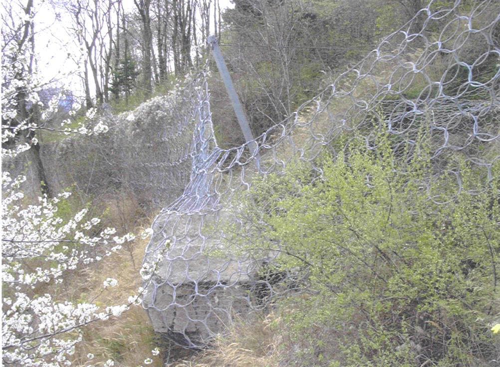
The Cost of Error: Why You Cannot Select a Barrier by "Rule of Thumb" Designing dynamic catch-type rockfall barriers is a process that leaves no room for rough estimates. Selecting the energy absorption capacity and height of a structure based solely on a visual inspection of the slope inevitably leads to either unjustified budget overruns (installing an excessively robust system) or the catastrophic failure of the barrier during the very first serious rockfall.
A sound design and reliable computer modeling are rooted in meticulous field data collection. Below is a comprehensive list of engineering survey materials required before initiating the design phase.
1. Topographic and Geodetic Surveys and Digital Elevation Model (DEM) To mathematically model the exact falling trajectory of a rock, geotechnical engineers require an accurate 3D model of the slope.
What is required: A high-precision Digital Elevation Model (DEM), topographic plans (typically at a scale of 1:500 or 1:2000), and characteristic cross-sections of the slope (from the potential detachment zone to the protected asset).
Why it is needed: The presence of micro-relief (benches, gullies, local elevations) critically influences the fall trajectory. Precise slope geometry makes it possible to calculate the acceleration zones of the block and its bounce points, which directly dictate the barrier installation location. In modern practice, aerial LiDAR scanning via UAVs is widely used to obtain this data.
2. Engineering and Geological Characteristics of the Rock Mass (Threat Source) It is crucial to clearly understand "what exactly" will fall. To this end, geologists investigate the upper part of the slope (the detachment zone).
What is required: Data on the lithological composition of the rocks, rock density, degree of weathering, and fracturing (jointing).
Primary parameter: Determining the parameters of the design block (the maximum possible solid rock fragment capable of detaching from the rock mass). The designer needs the exact volume (in cubic meters) and rock density to calculate the boulder's mass in tons.
3. Soil Characteristics in the Barrier Installation Zone The barrier must not only catch the rock but also remain in place by transferring the immense pull-out load to the foundation soil.
What is required: The physical and mechanical properties of the soils directly along the proposed barrier installation line.
Why it is needed: The structural posts and wire rope retaining cables of the barrier are secured using deep ground anchors. The soil type (solid rock, highly fractured rock, scree, or clay) dictates the choice of anchor type (bar, cable, self-drilling), its diameter, installation depth, and the volume of grout required. Without this data, it is impossible to guarantee that the barrier will not be uprooted along with its anchors upon impact.
4. Kinematic Parameters (Result of Computer Modeling) Based on the collected topographic and geological data, engineers simulate the rockfall in specialized software (e.g., RocFall). At this stage, the specific data used to select the barrier model is determined:
Kinetic energy (kJ): Calculated based on the block's mass and its velocity at the interception point. This defines the barrier's energy absorption class (from 500 to 8,000 kJ and beyond).
Bounce height (m): The maximum height at which the block flies above the ground surface at the barrier installation location. This parameter strictly dictates the required effective height of the catch fence (from 2 to 8 meters).
Conclusion The selection, modeling, and design of rockfall barriers is a complex engineering task. Only the availability of an up-to-date DEM, precise data on the design block's mass, and the physical and mechanical properties of the soil make it possible to develop a system that will reliably protect infrastructure and human life. Cutting corners on pre-design surveys is unacceptable in geotechnics, as high-quality initial data is the bedrock of dependable engineering protection.